Table of Contents
Introduction
The AWE Core OS™ is an embedded library enabling Audio Weaver signal processing and remote tuning on devices with Operating Systems. This document describes the theory of operation and the basic concepts of Audio Weaver and AWE Core OS.
The AWE Core OS™ deliverable consists of a set of libraries that can be linked to an application running in a rich OS environment, such as Linux.
What is AWE Core OS?
AWE Core is a data-driven engine. It contains a set of signal processing modules. The signal processing logic, which referred to as a ‘layout’, is constructed at runtime using a set of commands that configure and connect some subset of these modules. Commands add modules to the active layout, connect wires between modules, configure module parameters, and start/stop audio processing.
Note: a signal processing Layout is completely defined by a set of tuning commands.
The process of instantiating a layout using a is referred to as dynamic instantiation. The following is a set of tuning commands that dynamically create a signal processing layout...
0,create_wire,wire1,48000,2,32,0,32,0,4,0,0
0,create_wire,wire2,48000,2,32,0,32,0,4,0,0
0,create_wire,wire3,48000,2,32,0,32,0,4,0,0
0,bind_wire,wire1,Input
0,bind_wire,wire2,Output
0,create_module,SYS_toFloat,ModuleTypeConversion,1,1,0,wire1,wire3,1,0
0,create_module,SYS_toFract,ModuleTypeConversion,1,1,0,wire3,wire2,0,1
During signal processing development these commands are created by Audio Weaver Designer™. MATLAB scripts, 3rd party tools, or other scripts such as Python.
For a product to run stand-alone, the complete set of commands that defines a Layout (both in topology and tuning) is exported by AWE Designer as an “Audio Weaver Binary” (.AWB) file or a C-array with the commands listed in ASCII hex. These commands can then be stored in non-volatile memory or compiled in as a C-array.
Data Interfaces
AWECore exchanges three types of data; Audio, Tuning, and Control.

Audio data Audio data is processed by the AWE Core OS signal processing engine.
Tuning data dynamically configures or polls the signal-processing, including the topology of the modules and the tuning parameters for each, such as filter coefficients or channel gain. This data is in the form of commands, typically issued by Audio Weaver Designer™ (or 3rd party tools / scripts).
Control data consists of parameters exchanged between firmware components and the Audio Weaver signal processing logic. This data can be used to, for example, light an LED if the audio level passes a certain threshold.
Tuning Model
A signal-processing Layout is instantiated in AWE Core OS through a set of commands. From the perspective of the integrator and system designer, there are two scenarios to understand - based on the origin of the commands.
Design-Time: First, while a new product is being developed, DSP Engineers, Acoustic Engineers, and System Engineers will use PC-based tools like AWE Designer to create and refine the signal processing Layout. During this phase, tuning commands are sent to the AWE Core from the PC in realtime.
Standalone: Later, when developers are done tweaking and tuning a product’s signal-processing Layout, the commands that instantiate it may be compiled in to the application as a C array, or saved to the file system on target.
Design-Time Operation
When using AWE Designer to create and tune a signal processing layout, tuning commands (and the resulting replies) are exchanged between the PC and the AWE Core OS running on the target hardware. The full path that these tuning commands travel is shown below.
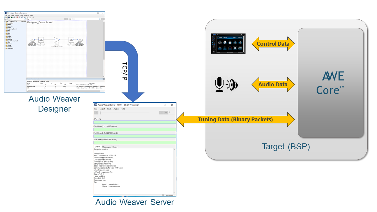
Communication between Designer and Server uses plain text commands. AWE Server then converts each text command into a binary packet and sends it to the target platform over the specified tuning transport (e.g. Ethernet, USB, RS232, etc.). Scripts containing the text commands are called Audio Weaver Scripts (AWS). Scripts containing the binary commands are called Audio Weaver Binary (AWB) scripts.
For a more detailed description of our Tuning Protocol and the AWB command structure, please see the Tuning Protocol document here. Also review the built-in TCP/IP based tuning interface here: aweOS_tuningSocketOpen
Note that this command protocol is strictly initiated by the host (typically AWE Server). The host issues a command and will not issue another command until the original command is complete or times out. The firmware can never issue a command. It can only respond with a single reply to the current command.
Standalone Operation
Once configuration and tuning is complete, a layout can be saved on the product to allow stand alone operation. To do this, the Layout is exported as an Audio Weaver Binary (.AWB) file or as a C Array (C file and Header file). In AWE Designer, select Tools / Generate Target Files. AWB’s may be stored in-product in two ways: either ‘compiled-in’, where the AWB is embedded as static data in the application itself, or stored as an .AWB file on the filesystem.
AWB From File
Compiled-in AWB
Another way to store and load an AWB is to use Audio Weaver Designer to generate a C array that will be compiled in to the application. The array is then loaded (i.e. executed) immediately after starting the program, and audio processing starts immediately with no need for external activity.
Audio Weaver Designer will automatically generate this pre-initialized array in a .C file by selecting Tools -> Generate Target Files.
To load a layout that has been stored in a C array in the application, call aweOS_loadAWBFromArray.
Control Model
API functions are provided to allow the firmware to directly interact with modules by setting/getting their variables and execution status.
- Control and query values of module variables aweOS_ctrlSetValue
aweOS_ctrlGetValue
aweOS_ctrlSetValueMask
aweOS_ctrlGetValueMask
- Control and query module status aweOS_ctrlSetStatus
aweOS_ctrlGetStatus
- Convert a module handle to module class aweOS_ctrlGetModuleClass
Collectively these API functions are referred to as the Control Interface.
Audio-Processing Model
Block Processing
As audio samples are received by calls to aweOS_audioImportSamples, they are buffered into blocks. These blocks of audio samples are then copied into the AWE Core OS system where they are processed.
A fundamental concept for AWE Core OS is that the layout signal processing block size can differ from the fundamental block size. For example, the audio device may be configured for a block size of 32 samples, while a signal processing layout may use a block size of 64, 96, 256, etc. The only limitation is that the layout block size must be an integer multiple of the DMA block size. This decoupling allows the DSP engineer to easily make tradeoffs between MIPs, memory, and latency without having to modify or rebuild the application code. As shown in Figure 13, the AWE Core OS system has internal buffering to automatically handle this decoupling. In the example in Figure 3, the signal processing layout operates on blocks 4x the fundamental block-size.
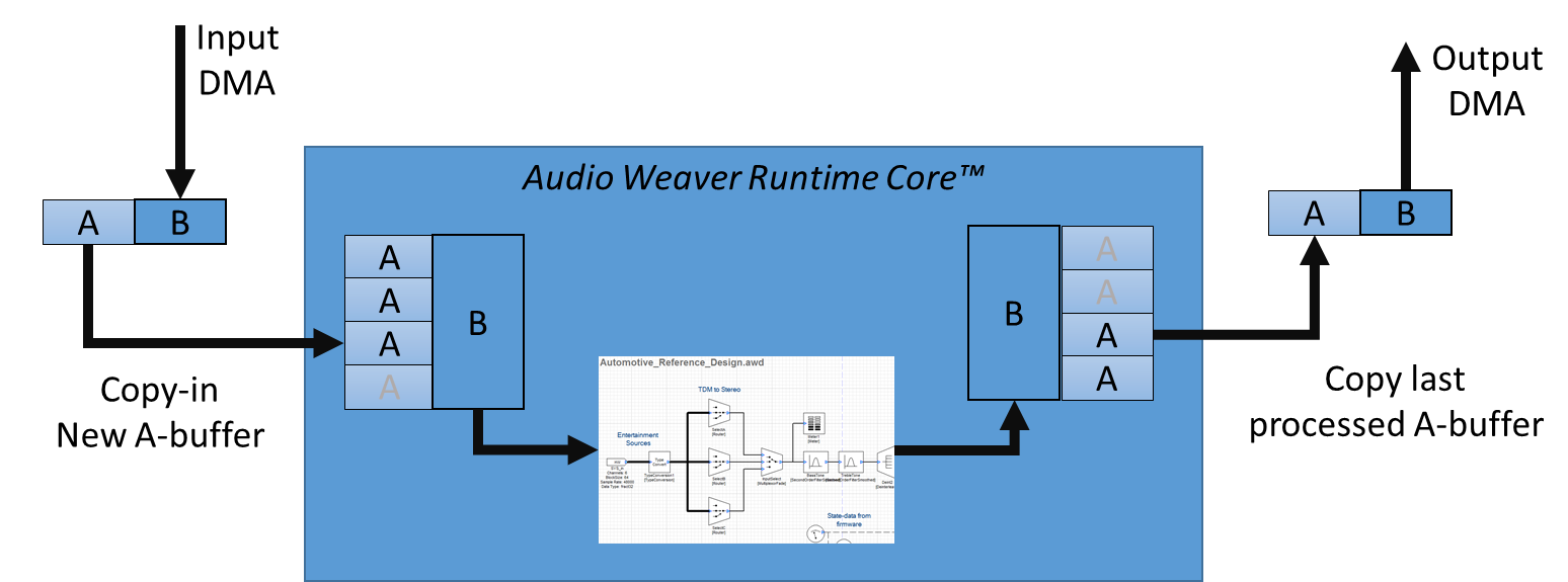
The following steps illustrate the audio processing.
- When an audio frame is received it is copied from the receive buffers to the input buffers of the AWE Core layout.
- Likewise, since input and output are synchronous, newly processed audio is copied from the AWE Core layout output buffers to the hardware output buffers.
- When the number of audio frames accumulated matches the number of audio frames needed by the layout, the layout is processed.
